Tuesday, July 05, 2005
Build your own Chat-Cord
Build your own Chat-cord
…or Using your old plain telephone to call over the Internet.
…or VoIP meets POTS
| Free conferance call,Internet telephony with Skype, Skype, , chatcord, VoIP,Voice over IP, save, new,cordless, Free phone calls, chat-cord, IP Phone, Skype compatible, free voip, dualphone, VoIPBuster | by Jeroen aka Mr. Blond All pictures are clickable for |
 Voice over IP is taking over the world and I also like the idea of calling for free… The problem I’ve experienced so far is the fact that you always have to use those cumbersome headsets. When it would be possible to use your standard phone for this application, the experience of VoIP would be much more like the real POTS (plain old telephone system). Especially a cordless phone with the base station near the pc would be nice. Furthermore it would be desirable to be able to use your normal phone keys to control Skype (or any other VoIP program). Voice over IP is taking over the world and I also like the idea of calling for free… The problem I’ve experienced so far is the fact that you always have to use those cumbersome headsets. When it would be possible to use your standard phone for this application, the experience of VoIP would be much more like the real POTS (plain old telephone system). Especially a cordless phone with the base station near the pc would be nice. Furthermore it would be desirable to be able to use your normal phone keys to control Skype (or any other VoIP program).Christoffer Järnåker actually did a nice job eliminating this shortcoming with his Siemens Skype phone, www.grynx.com/index.php/projects/siemens-skype . The disadvantage of this technique is that you kind of ruin your phone and that the procedure to create this kind of phone is different for every single type of phone. |
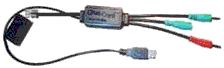 Not too long ago I ran across a device called Chat-Cord (www.chat-cord.com). Not too long ago I ran across a device called Chat-Cord (www.chat-cord.com).This device does actually the same thing but it is placed between you phone and pc, not modifying your phone. But… This device is pretty expensive and I couldn’t get it here in the Netherlands. Furthermore it seemed to me that this device actually isn’t very complicated. So, after some internet research I somewhat found out how it worked and identified two difficulties to be solved. |
 In this article a description is given how to make your own chat-cord. It costs In this article a description is given how to make your own chat-cord. It costsonly like 7 euros. You have to solder some parts but it is very basic and simple. To be able to use a normal phone to connect to the pc we have to make it look like for the phone as if it were connected to a normal telephone line and this telephone line has to look like it is making a call. First of all the normal telephone line has a certain voltage, depending on the state of the line. On hook (waiting for incoming calls) is like 60V DC, ringing is 100V AC (roughly 100Hz) and off hook (an active call is going on) around 9V DC. So to be able to use a normal phone to make it think a call is going on, the phone has to see a 9V DC voltage at its input. This can simply be achieved with a 9V battery. An alternative to this is to power the device from your USB port. It will only provide you with 5v instead of 9v, but this works fine in most cases. You have 300mA to your disposal there and that is more then enough. Just make sure you connect the right wires |
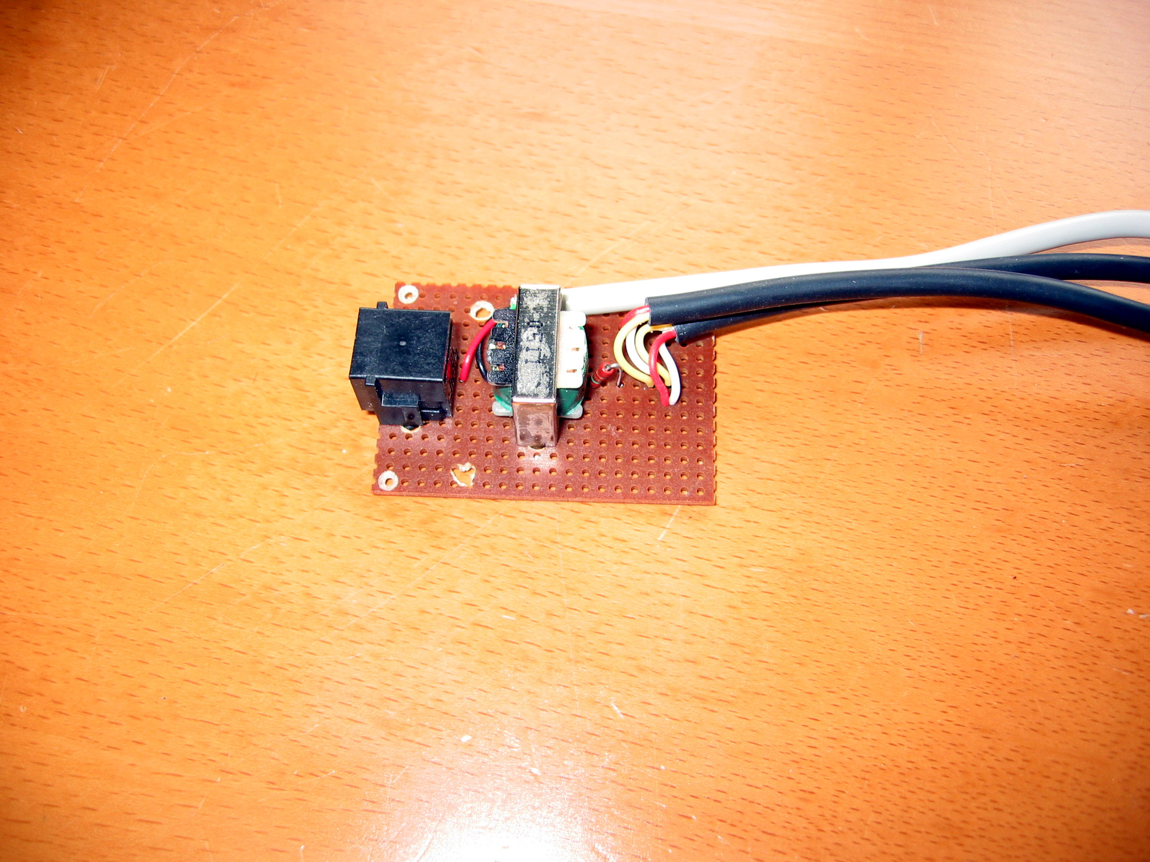
| The second part is the tricky part. A normal telephone system uses only two wires to send both the microphone and the speaker signal. From basic electronics you might know that you need 2 wires to send a signal, and at least 3 to send 2 signals, because one of the wires is acting as a reference (usually called ground). In a telephone system both the mic and the speaker signal are multiplexed into one signal. To be able to connect your phone to you mic-in and line-out of your pc you have to de-multiplex these signals. The solution of Chris was to extract the mic an speaker signal before it is multiplexed inside the phone. But this can also be done by a transformer (which is also used to prevent the 9V DC from going into you soundcard). The kind of transformer used for this application is a so called secondary centre tapped transformer. Meaning that it has 2 connections at its primary side (where the telephone will be connected) and 3 connections at its secondary side. The middle connection is physically connected to the middle of the secondary coil of the transformer. This middle connector is used as a shared ground for both the mic and the line-out.  Another issue is the input impedance of a phone line. When a phone line doesn’t see the right input impedance reflections will occur, resulting in echoes or even in disabling the line. A telephone line has a input impedance of 600 Ohms, so the transformer has to be a 600 Ohm transformer. At the secondary side of the transformer a 150 Ohm resistor has to be placed at the middle connection to make the secondary input impedance 600 Ohm as well, resulting in a balanced transformer. This all might seem complicated but as can be seen from this figure, the circuit is pretty simple and small. |
 For the connection to the pc jack-plugs have to be used, usually these are For the connection to the pc jack-plugs have to be used, usually these arestereo. For the microphone connector the left and right signal can be simply connected to each other at the circuit connection, so actually you make it a mono signal. For the speaker connection one of the left or the right signal should not be connected because your soundcard stereo output would be shortcut otherwise. (In most scenarios this won’t matter though as the sound from both channels are the same.) One funny thing is that it doesn’t matter which connector you plug into mic or headphones. The result will be the same as we have the transformer in-between the two cables. For the telephone connector a RJ11 female connector should be used, so you can attach any phone to your device. Everything can then later be put into a nice little box, and -hey!- let’s use a ADSL splitter. It will provide us not only with the RJ11 that we need but also a neat little box. |
 The software from Chat-Cord to be able to control Skype with your normal The software from Chat-Cord to be able to control Skype with your normaltelephone keys ( www.chat-cord.com/downloads.htm ) works perfect with the circuitry, meaning that you can make and accept calls with your normal phone (not necessary to be at the pc when you make or accept a call). The only thing you need to do is to assign shortcut keys in Skype to your different contact persons, so you can call them with that number. Actually all this software does is to convert the DTMF signals from you phone (the different bleeps) to numbers , # and *. I’ve tried the circuit with four different phones normal wireless, DECT, and wired and it all works perfect. You have a little bit of crosstalk between speaker and microphone (you hear yourself talking) but this is normal in telephony and it can be decreased with the volume control setting of your microphone (make sure you turn off the mic. boost). |
 So, let go through the steps in building one of these. I’m going to use a 9v battery as this is more ‘fool proof’, but if you’re confident that you know what you’re doing then go ahead an use power from the USB port. This can either be build on a circuit board (like on the pictures) or like a bird nest. A bird nest means that you solder the wires directly on to each other and it doesn’t look as good, but for a small project like this it should do fine.
If you want to use an USB cable as power source then cut it off and strip down the wires. You will have red, back, white, green and a shield. Cut of white and green as we won’t be using them. Red is +5v and black is ground. The shield can also be cut off, or if the transformer has a metal casing then you can connect it there. This would provide some extra shielding. |
The following parts are needed for the circuit and the amounts I paid for it are as follows
| 9V battery | €1.50 |
| 600 Ohm - 600 Ohm 1:1 transformer secondary centre tapped | €2.50 |
| 150 Ohm resistor | €0.10 |
| Stereo jack cable (cut it in half to be used as mic and speaker plug) | €2.00 |
| Print board 5×5cm | €0.50 |
| €6.60 |
 If you can’t find a transformer that is centre tapped only at the secondary side If you can’t find a transformer that is centre tapped only at the secondary sideyou can also use a transformer centre tapped at both sides and just not use the middle connector at the primary side (I also did this because I couldn’t find a transformer centre tapped only at the secondary side). Just make sure it is a 600-600 Ohm 1:1 transformer. If you choose to use a battery in the circuit, it will last for a long time because no power is extracted from it during a call (otherwise we would be able to extract all our power from the telephone company Theoretically you need at least 6v to the telephone but USB delivers 5v so what could be done then is to insert an IC that transforms 5v DC to 9v DC (a so called step up converter or DC-DC converter). In most cases the provided 5v will be sufficient, and if not - just hook up a 9v battery |
Good luck!!
And have fun Skyping all around the house…
For questions you can reach me at: mr_blond18@hotmail.com
rapidbox skype adaptor voip voice over ip,Go wireless with Olympia Cordless DUALphone, CyberPhone,skype usb phone rj11 adapter, cordless dualphone, FWD, Skype, Xten, Yahoo, Stanaphone, TerraCall pc mac laptop,VoIPBuster
source:http://www.grynx.com/index.php/projects/build-your-own-chat-cord/
![]()
